
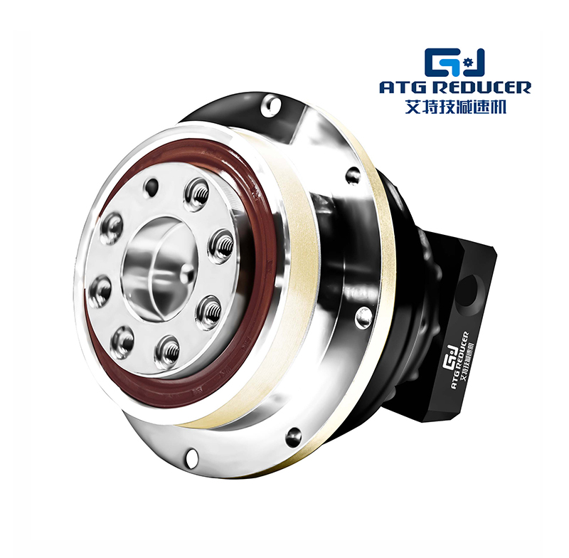
An ATG gear reducer is commonly understood as an industrial gear reducer used to lower input speed and increase output torque in machinery and power transmission systems. In many applications, the term is associated with compact, durable, and efficient gearbox solutions for conveyors, mixers, material handling equipment, packaging lines, automation systems, and general industrial drives. For buyers, engineers, and technical teams, understanding gear reducer size and specifications is essential for selecting the right unit, avoiding overload, and improving long-term operating performance.
This guide provides a clear, SEO-friendly overview of ATG gear reducer size and specification information for industrial use. It covers definitions, sizing principles, technical parameters, common mounting types, reduction ratios, torque ranges, efficiency considerations, selection factors, and specification tables. The content is designed for direct use in a blog post, product category page, industrial directory page, or technical resource page. No company recommendations are included. The information below focuses only on industry-generic gear reducer knowledge.
A gear reducer is a mechanical transmission device that reduces rotational speed from a motor or input shaft while increasing torque at the output shaft. In industrial systems, this allows motors to operate more efficiently under load and enables machinery to perform tasks that require higher force at lower speed. An ATG gear reducer typically refers to this type of gearbox within a specific industrial naming context, but the core function remains universal across the gear reducer market.
Gear reducers are also called speed reducers, gearboxes, or reduction gearboxes. They are used where direct motor drive is not suitable because the equipment needs controlled speed, high torque, smooth motion, or precise positioning. Common industrial applications include:
Because industrial machines vary widely in load, duty cycle, and installation environment, gear reducer sizing must be matched carefully to the application. The right gear reducer size depends on torque, ratio, motor power, service factor, mounting style, and operating conditions.
Selecting the correct gear reducer size is one of the most important steps in power transmission design. A reducer that is too small may overheat, wear prematurely, produce excessive noise, or fail under peak load. A reducer that is too large may increase cost, occupy unnecessary space, and reduce system efficiency if not properly matched.
Proper sizing improves:
For search engines and technical readers alike, terms such as gear reducer size chart, gear reducer specification, reduction ratio, output torque, and mounting dimensions are highly relevant. These are the key factors used in actual selection and installation.
Gear reducer size is usually defined by a combination of mechanical and dimensional parameters rather than by a single number. In industrial catalogs and technical sheets, size may refer to frame size, center distance, torque rating, housing dimensions, or shaft diameter. For SEO and technical clarity, it is useful to understand the main ways gear reducer size is described.
| Size Parameter | Meaning | Why It Matters |
|---|---|---|
| Frame Size | General body size or series designation | Helps identify physical fit and capacity |
| Center Distance | Distance between gear centers inside the reducer | Indicates internal gear layout and capacity |
| Output Torque | Torque available at the output shaft | Determines load-handling capability |
| Shaft Diameter | Diameter of input or output shaft | Affects coupling and installation compatibility |
| Housing Dimensions | Length, width, height, and footprint | Important for machine design and space planning |
| Mounting Type | Foot, flange, shaft-mounted, or torque arm | Determines installation method |
In practice, buyers should review both the technical size and the performance specifications. A reducer may be physically compact but still provide high torque depending on gear type and ratio. Likewise, a larger housing does not always mean better performance unless the design, lubrication, and service factor are suitable for the duty cycle.
Different gear reducer types have different size characteristics and performance profiles. Understanding the main categories helps with selection and specification comparison.
| Gear Reducer Type | Core Feature | Typical Use |
|---|---|---|
| Helical Gear Reducer | High efficiency, smooth running, good load capacity | Conveyors, mixers, general industrial drives |
| Bevel Gear Reducer | Changes rotation direction, compact design | Right-angle drive systems |
| Helical Bevel Gear Reducer | Combines smooth transmission with right-angle output | Heavy-duty conveyor and automation systems |
| Worm Gear Reducer | High reduction ratio in compact size | Low-speed, moderate-load applications |
| Planetary Gear Reducer | High torque density, compact, precise | Servo systems, robotics, compact high-load equipment |
| Shaft Mounted Reducer | Direct mounting on driven shaft | Conveyors, bulk material handling |
Each reducer type influences size, efficiency, backlash, noise, and cost. For example, worm reducers are often compact and offer high ratios, but they may generate more heat and lower efficiency than helical or planetary designs. Helical reducers are widely preferred for general industrial use because they provide an excellent balance of durability, efficiency, and size.
A complete ATG gear reducer specification guide should include the technical data needed to compare units accurately. Below are the core specifications that matter most in industrial selection.
| Specification | Description | Selection Impact |
|---|---|---|
| Input Power | Motor power the reducer can accept, usually in kW or HP | Ensures compatibility with the drive motor |
| Input Speed | Motor speed in RPM | Used to calculate output speed and ratio |
| Reduction Ratio | Relationship between input and output speed | Directly determines final speed and torque |
| Output Speed | Speed at the output shaft in RPM | Must match application requirements |
| Output Torque | Twisting force at the output shaft | Critical for load capacity |
| Efficiency | Percentage of input power transmitted to output | Impacts energy use and heat generation |
| Service Factor | Safety multiplier based on duty severity | Improves reliability under variable loads |
| Backlash | Small amount of shaft play in the gear train | Important for precision applications |
| Noise Level | Acoustic performance during operation | Affects comfort and factory environment |
| Lubrication | Oil or grease type and maintenance interval | Influences life and maintenance cost |
While actual dimensions vary by design and manufacturer, industrial gear reducers are often organized into size series based on torque capacity and housing dimensions. The following table offers a general industry reference for common size ranges. This is not a brand-specific chart, but a practical overview for content, comparison, and SEO optimization.
| General Size Range | Typical Motor Power | Approx. Output Torque | Typical Applications |
|---|---|---|---|
| Small | 0.12–1.5 kW | 10–200 Nm | Light conveyors, small machines, packaging units |
| Medium | 1.5–7.5 kW | 200–1,500 Nm | General industrial equipment, mixers, feeders |
| Large | 7.5–30 kW | 1,500–10,000 Nm | Heavy conveyors, lifting systems, process machinery |
| Extra Large | 30 kW and above | 10,000 Nm and above | Mining, bulk handling, high-load industrial drives |
These ranges are helpful for early-stage selection and specification writing. The exact size required depends on the duty profile, start-stop frequency, shock loading, ambient temperature, and installation orientation.
The gear reduction ratio is one of the most important specification values in any gear reducer guide. It is the ratio between input speed and output speed. The basic formula is:
Reduction Ratio = Input Speed ÷ Output Speed
For example, if a motor runs at 1,450 RPM and the machine needs an output speed of 145 RPM, the required ratio is 10:1.
Higher ratios reduce speed more and increase torque more, but they may also affect efficiency, heat, and physical size depending on reducer type. Worm gear reducers often support high ratios in a compact housing, while helical and planetary reducers may provide higher efficiency at medium or high loads.
| Input Speed (RPM) | Desired Output Speed (RPM) | Required Ratio |
|---|---|---|
| 1,450 | 290 | 5:1 |
| 1,450 | 145 | 10:1 |
| 1,450 | 72.5 | 20:1 |
| 1,450 | 36.25 | 40:1 |
Output torque is the force that allows the driven equipment to move, lift, mix, push, or convey material. It is often the most important performance figure in gear reducer selection. The required torque depends on the machine load, operating speed, friction, incline angle, acceleration requirements, and shock conditions.
If torque demand is underestimated, the reducer may slip under load, overheat, or suffer accelerated wear. If torque capacity is correctly matched, the machine can operate smoothly and reliably over a long service life.
In technical literature, torque may be shown as nominal torque, rated torque, peak torque, or permissible torque. These values must be read carefully because they are not always interchangeable. A reducer used in intermittent duty may handle higher short-term peaks than one used continuously.
| Torque Term | Meaning | Application Note |
|---|---|---|
| Rated Torque | Torque the reducer can handle continuously | Main design selection value |
| Peak Torque | Short-term maximum torque | Relevant for startup and shock loads |
| Nominal Torque | Standard reference torque | Used in catalogs and comparison charts |
| Permissible Torque | Maximum safe torque under specified conditions | Depends on service factor and duty cycle |
Gear reducer efficiency refers to how much input power is successfully transferred to the output shaft. Higher efficiency means less power is lost as heat, which is especially important in continuous-duty systems and energy-sensitive industries.
Typical efficiency depends on gear type:
Efficient reducers reduce operating temperature, lower energy costs, and improve reliability. In modern industrial systems, efficiency is often a key purchasing criterion because it supports sustainable operation and reduced lifecycle cost.
Mounting style affects both the physical size and the installation method. The reducer must fit the machine layout and support the required shaft orientation.
| Mounting Type | Description | Typical Use |
|---|---|---|
| Foot Mounted | Base-mounted housing with bolt holes | Common industrial machines and conveyors |
| Flange Mounted | Mounted by flange interface to equipment | Compact installations, direct machine mounting |
| Shaft Mounted | Reducer mounts directly on the driven shaft | Bulk handling and conveyor drives |
| Torque Arm Mounted | Reaction arm controls housing movement | Heavy-duty shaft-mounted systems |
| Vertical Mounted | Designed to work in vertical orientation | Specialized lifting and process equipment |
Installation orientation should always be confirmed before final selection. Some reducers are designed for horizontal mounting only, while others allow multiple installation positions with proper lubrication control.
The following sample specification table shows the kind of data commonly found in an ATG gear reducer size and specification guide. It is intended as an industry reference format, not as a product listing.
| Specification Item | Typical Range | Unit |
|---|---|---|
| Input Power | 0.12 to 200+ | kW |
| Input Speed | 750 to 3,600 | RPM |
| Reduction Ratio | 3:1 to 10,000:1 | — |
| Output Torque | 10 to 100,000+ | Nm |
| Output Speed | 0.1 to 500 | RPM |
| Efficiency | 65% to 98% | % |
| Service Factor | 1.0 to 2.5+ | — |
| Operating Temperature | -20 to 40+ | °C |
| Lubricant Type | Mineral oil / synthetic oil | — |
| Protection Level | IP54 to IP66 | — |
A properly selected gear reducer offers several benefits in industrial drive systems. These advantages make gear reducers a fundamental component in mechanical power transmission.
For industrial SEO content, phrases such as high torque gear reducer, compact gear reducer, industrial gearbox, and gear reduction solution are commonly searched and highly relevant to buyers researching equipment options.
Proper gear reducer selection is based on application data, not just motor power. A structured approach improves accuracy and prevents oversizing or undersizing. When reviewing ATG gear reducer size and specification information, consider the following factors:
The best selection is not always the largest size. In many cases, the optimal reducer is the one that matches torque demand, speed target, and environmental conditions with the right service factor and efficiency level.
Before finalizing a reducer choice, use a technical checklist to confirm that the gearbox meets the application requirements.
| Checklist Item | Confirmed? | Notes |
|---|---|---|
| Motor power and RPM | Yes / No | Input data should be verified |
| Required output speed | Yes / No | Must match process requirement |
| Required output torque | Yes / No | Include peak load if applicable |
| Reduction ratio | Yes / No | Confirm exact or close standard ratio |
| Mounting arrangement | Yes / No | Foot, flange, shaft, or torque arm |
| Shaft dimensions | Yes / No | Check bore, keyway, and coupling |
| Ambient temperature | Yes / No | Important for oil selection and thermal limits |
| Ingress protection | Yes / No | Needed for dust or washdown environments |
| Lubrication method | Yes / No | Oil bath, splash, or forced lubrication |
| Service factor | Yes / No | Use higher value for shock or heavy-duty load |
Gear reducer performance depends not only on selection but also on correct operation and maintenance. Regular inspection improves reliability and helps preserve rated size and torque capacity over time.
Important maintenance considerations include:
Overheating, contamination, and misalignment are common causes of gearbox failure. Good maintenance protects the reducer size rating, improves service life, and reduces downtime.
If you are building an industrial blog, category page, or directory page, the following terms are relevant for search visibility and topic coverage. They can be used naturally throughout the page:
Using these keywords in headings, tables, paragraphs, image alt text, and metadata can improve topical relevance and help the page rank for gearbox-related industrial search queries.
An ATG gear reducer size and specification guide is a practical resource for understanding how industrial reducers are selected, compared, and applied. The right reducer size is determined by torque demand, speed reduction ratio, efficiency, mounting format, and environmental conditions. Whether the application involves a conveyor, mixer, packaging machine, or heavy-duty industrial line, the key to successful selection is matching technical specifications to real operating needs.
For SEO-focused industrial content, a strong gear reducer page should include clear definitions, size ranges, specification tables, ratio formulas, torque details, mounting options, and maintenance guidance. These elements improve both user experience and search engine visibility while keeping the content useful, original, and structurally organized.
Use the tables and sections above as ready-to-insert HTML content for your blog, category page, or technical industry page. The material is generic, informative, and optimized for search-oriented industrial publishing.
Этот веб-сайт использует файлы cookie, чтобы обеспечить вам максимально эффективное использование нашего веб-сайта.

 Chinese
 EN
EN Español
 Deutsch
 Tiếng Việt


 телефон
Комментарий
(0)